The Model scale 1/35°
The model of U-47 is with ballast, for static or dynamic, and radiocontrolled diving.
1°) Building
1-1°) What the kit is made of:
* 1 hull polyester 1, 92m,
* 1 higher brass 8/10 bridge precut in 3 parts (according to plans of the kriegsmarine),
* 1 standard coning tower VII B with cut out brass floor,
* 1 set of upperworks.

1-2°) The assembly:
The installation of the bars of diving, the rudders and the propeller shafts is done without too many difficulties, as on the majority of the sailing models. The skittle strongly should be leaded, with approximately 6 kilos of lead.

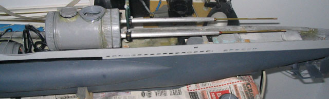
Adjustment of the interior of the hull.
We do not see large-thing, it is a little bazaar on my bench, but other more precise photographs will arrive soon!
1-3°) The ballast:
It is the principle of glass turned over in a sink full of water, which fills only if we make a hole above...
In the model, it is a PVC tube stopped at the ends, perfectly tight. A hole of admission and drainage of water is bored below. Above, a " three ways " valve allows a setting in the open air of the ballast to admit water, and thus to weigh down the model to make it diving; conversely, it also makes it possible to admit gas coming from a bottle under pressure, in order to drive out the water of the ballast, and thus to make raise the submarine.

 |
The drawer valve
is controlled by a stem connected to a servo unit. |
 |
Valve
in neutral position: the ballast does not fill,
nor is emptied: the submarine is balanced. |
 |
The servo order
filling of the ballast: the air
contained in this one is evacuated, replaced by water, there penetrating
by the hole under this one. |
 |
The servo order the water draining of the ballast; the gas exerts a pressure on the top of this one, which is evacuated by the hole under the ballast. |
2°)Sealing
2-1°) Guiding principle:
My preceding submarine, U-995, had a single tight hull inside. It is what caused its loss. The great volume of this tight hull did not authorize any flees, that it is of water or gas of the lead-acid battery (see the page concerning these facts). For U-47, the idea is to only seal off what needs some, and to flood the remainder of the hull.
2-2°) Use of electric connection boxes and PVC pipes.
A box contains the receiver and its accumulators, another box contains servo front elevators, another box contains the servo ordering the valve of the ballast, another box contains the micro-servos of the back elevator as well as rudder.
A PVC tube diameter 80 has been used to make an engine room, it contains the two engines as well as the speed regulator.
 |
2 motors SPEED 540; 16000 rpm demultiplicated at 2.33; alimentation 7,2 volts; parallele assembly. |
 |
Electronic regulator ROBBE 20 amps; go front and back; a little oversize! |
 |
Assembly of the engines, the regulator,
the switch of startup and the catch of load, in a tube PVC 80 mms diameter. |
 |
The two engines are fixed perfectly
in the tube. |
 |
The tube is closed, it does not remain to fix the stoppers of visit and to fix the propeller shafts. |
 |
The propeller shafts are placed in tubes of stern post; the sealing is ensured by grease injected
into the tubes by the two |
Final
result: |
|
 |
|
The interior of each one of these boxes is accessible
by a tight stopper, as you can see it in the compartment postpones photograph
above. The lead-acid battery, it was replaced recently by six accumulators
Ni-Mh, positioned inside two tubes PVC, 40mm diameter. Autonomy is more important,
the risks of hydrogen degasification are, in my opinion, non-existent.
